
DISC SPRINGS DIN 2093 / DIN EN 16983
DIN 2093 springs (actually DIN EN 16983) are conical washers with elastic properties. They are commonly known as disc springs but sometimes they are called belleville washers. These springs are manufactured according to the specifications of DIN 2093 / DIN EN 16983 standard, which establishes all the characteristics these pieces have to meet.
The main feature of DIN 2093 /DIN EN 16983 disc springs is the capacity to generate high spring load compared to traditional helical springs, in small enclosures and with short displacements. These spring washers are under small deflection when submitted to large loads. Serial or parallel assembly allows us to obtain higher defections and loads.
Their elastic properties allow them to work both in dynamic and static applications.
In the table of Disc spring cathegory all standard disc springs of our catalogue are shown. Springs in other dimensions can be manufactured upon request.
Series
Some springs are classified as A, B or C. This classification corresponds, according to DIN 2093 / DIN ES 16983 standard, to a specific relation between the external diameter of the disc spring and its thickness. The three series for each standard measure are established:
- Series A : OD/t ≈ 18; high load springs
- Series B : OD/t ≈ 28; medium load springs
- Series C : OD/t ≈ 40; low load springs
In this way, for each external diameter of the springs defined, according to the standard, there are three versions of that spring with different load. This is the reason why it is usual to refer to these standard springs by the letter and external diameter (p.e. A-50 or B-71). Apart from the three series, other thicknesses can be manufactured for a specific diameter, that although they comply with the standard they do not correspond to any of the three series.
Supporting surface
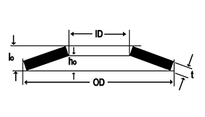
DIN 2093 (actually DIN EN 16983) standard recommends those discs whose thickness is higher that 6 mm to be manufactured with a supporting surface. Supporting surfaces increase the contact area between the plates helping tensions to be distributed. Reduced thickness (t’), which is usually different from the theoretical thickness (t), should be considered in springs with supporting surfaces. This is very important when designing stacks with these springs because it may affect the stack total height (parallel stack).
We can see in the product catalogue that the same disc spring is with or without supporting surfaces. In many cases, both springs can perform the same function successfully. However, different springs should be used depending on the application and the way to use it.
Definitions:
| Disc spring without supporting surface | Disc spring with supporting surface |
 |
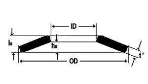 |
OD: Outside diameter
ID: Inside diameter
t: Thickness of the spring material
t’: Reduced thickness of the spring material for disc springs with supporting surfaces.
ho: Spring maximum deflection
lo: Spring total height (lo = t + ho) or for springs with supporting surface (lo = t’ + ho)
F(0,75 ho): Load in Newtons which returns the spring at 75% of its displacement or bending.
Serial or parallel stacks

Disc springs can be stacked in different ways, obtaining springs with the characteristics of load and displacement we may determine. There are two stack ways:
-
Serial stack: In this case, springs are staggered. With this type of stack, the load provided by one piece is maintained but the displacement is increased in direct proportion to the number of springs used in it.
-
Parallel stack: For this type of stack, the springs are placed in the same direction. The result is a spring with the same displacement as the spring with only one piece, but the load increases in proportion to the number of springs in it. In this type of stack, the loss of load due to friction produced between the pieces should be considered. Finally, stack with washers with different thicknesses is also possible or with combinations of parallel springs in different quantity. In this way, we will obtain springs whose load curve vs displacement will be composed of sections of different rigidity. This is because springs with lower thickness and therefore offering lower resistance to the load applied, will the first ones to displace until flattening; springs with higher thickness, as they offer higher resistance, will cause from that point an increase in the load needed to obtain an equivalent displacement.
The correct performance of disc spring stack mainly depends on its correct assembly. Hysteresis or frictions produced between the pieces and between the pieces and the stack guidance system may alter the load curve and displacement.
Through the calculation program, (it is possible to download in the CALCULATION PROGRAM section of the menu) calculations on stack can be made.
Combined serial and parallel stack can be made. This gives, obviously, springs whose load will result from multiplying by the number of pieces placed in parallel and with a total travel resulting from the number of groups of pieces (the ones placed in parallel), that are serial stacked. In these theoretical results, appropriate corrections due to hysteresis should be made.
Guidance and lubrication
The correct performance of disc spring stack mainly depends on its correct assembly. Hysteresis or frictions produced between the pieces and between the pieces and the stack guidance system may alter the load curve and displacement.
The most common guidance for disc spring stack is through its internal diameter, carried out through an internal shaft to the pieces. It is also possible to carry out an external guidance through a socket or another fixing way of the springs.
In both cases, it is important to respect the tolerances recommended in DIN 2093 /DIN EN 16983 shown in the table below:
| INTERNAL OR EXTERNAL DIAMETER in mm | Tolerance according to DIN 2093 in mm |
| Up to 16 | 0.2 |
| > 16 to 20 | 0.3 |
| > 20 to 26 | 0.4 |
| > 26 to 31.5 | 0.5 |
| > 31.5 to 50 | 0.6 |
| > 50 to 80 | 0.8 |
| > 80 to 140 | 1.0 |
| > 140 to 250 | 1.6 |
In the guidance elements, the surfaces in contact with the pieces should be polished and hardened at least at 55 HRC in 0.80 mm in depth.
In long stack, it could be necessary to introduce disc separators to avoid the buckling effect that would produce an increase in friction.
It is essential to use correct lubrication for the contact of the pieces with the guidance system and between the pieces. Depending on the work environment, the ways of lubrication are different. We can use oils, greases, powders containing molybdenum disulphide or other lubricants depending on needs.
In the cases where the friction produced by the guidance system may be critical for the application, there is the possibility to carry out special guidance by means of screws or balls placed between the pieces. For this type of guidance it is necessary to machine the pieces to insert the guidance elements. Through these systems, friction can be reduced but not eliminated completely.
Fatigue and relaxation
As disc springs are flexed, they withstand a certain level of tension, which is higher in some points of their geometry than in other points. This is due to the deformation produced when acting as a spring. Depending on the level of tension the piece is submitted to and the number of work cycles, the spring will accumulate a level of fatigue, until the breaking point, which will determine the stack useful life.
It is not possible to foresee fatigue with accuracy because it depends on many factors. However, based on the displacement suffered by the piece, the origin and final points of the travel, it is possible to carry out an approximation to the number of cycles the spring can withstand. The greatest use of this type of calculations is when we have to choose between two or more configurations of disc spring stack to select which one is suitable for an application.
Basic recommendations to make the life of a stack longer are: pre-stressing of at least 15% of its travel and not going beyond 75% when the dynamic load is applied.
When analysing the fatigue, it is necessary to point out the importance of the type of steel and thermal treatment used for manufacturing the piece. Austenising is one of the treatments that provide disc springs with better elastic qualities. However, tempering processes used together with “shot peening” offers excellent results, too.
Finally, it is important to point out that disc springs which are under constant compression loads for a long time will suffer from relaxation, which will produce a reduction in load. In order to minimise this relaxation, disc springs, over their manufacture process, are under a pre-setting process, as established by the DIN 2093 standard (actually DIN EN 16983). In this process, they are completely flattened and those that are not able to recover their initial height are discarded.
Relaxation, the same as fatigue, cannot be determined with accuracy, except in practice, because it depends on many factors, from temperature to the spring dimensions, compression level and time. However, we may consider as an approximation that stacks tends to loose its load by 5% during the first two weeks from being assembled, from that moment on, it should stabilize being the loss of load insignificant from then.